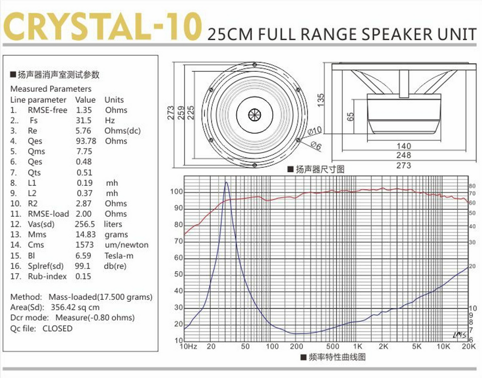
While designing a speaker using a full range driver, I ran into a common problem: the sensitivity shifts upward at a specific point making the higher frequencies output more decibels than lower frequencies. This problem is not unique to these drivers, though. Baffle step is another instance where this can occur. This can cause lower frequencies to drop significantly, which will suck the bass right out of your speaker. There is a solution to these problems: shelf filters.
Lii Audio Crystal-10; Example of full range driver with lower end having less sensitivity
Baffle step is the effect caused by the interaction of the driver and the baffle. It can cause lower frequencies to drop in sensitivity. This is due to a cancellation effect caused by sound wave interference from the point source and the diffraction effect from the cabinet edge. You can compensate by changing how the cabinet and baffle is shaped. But there is also shaping the signal to compensate for the effects.
In comes the importance of shelf or shelving filters. Many know about high pass filters and low pass filters, along with band-pass filters. Arguably, you should always use band-pass for sub-woofers, woofers, and mid-range drivers, but that is for another discussion. One that fewer know about, at least outside of electrical engineering (and even among some engineers), is the shelving filter. The shelving filter boost or attenuate the signal across a period of frequencies to flatten the signal.
Terminology for Shelf Filters
I discovered this filter while perusing the website of SiegfriedLinkwitz (yes, the one who created, with his friend from HP—Riley, the Linkwitz-Riley filter which is a pair of cascading Butterworth filters). But, he did not fully discuss the ways to describe this type of filter.
The Highs and Lows
A shelving filter is first divided into the categories of “low shelf filters” (“LSF”) and “high shelf filters” (“HSF”). This is identified by which part of the signal is being augmented. If you are increasing or attenuating sensitivity of the lower end frequencies, that would be an LSF. If you are decreasing or increasing the sensitivity at the higher end, that would be a high shelf filter.
The Boost and Cut
These are then further divided into two types—a boost and a cut type. So, when you are discussing the type of filter you are using, if you are compensating for baffle step through boosting the low end, you would call it a low shelf boost filter or an LSF boost. If you are cutting the high frequencies, then it would be a high shelf cut filter or HSF cut.
In practice, as regards implementation, you are primarily only using two variations of the circuitry. But it is still important to properly term what you are doing so that everyone is on the same page. Why only two variations? Because an HSF boost is a curve that resembles an LSF cut. Meanwhile, the LSF boost resembles the HSF cut. Why? Because when you raise one, the other end will be lower and vice versa. So, in practice, you are dealing with two filters, but the terminology separates them into four categories. Just be mindful of this in practice.
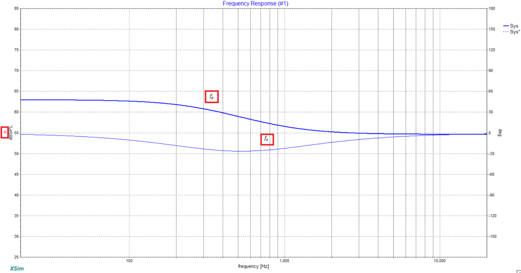
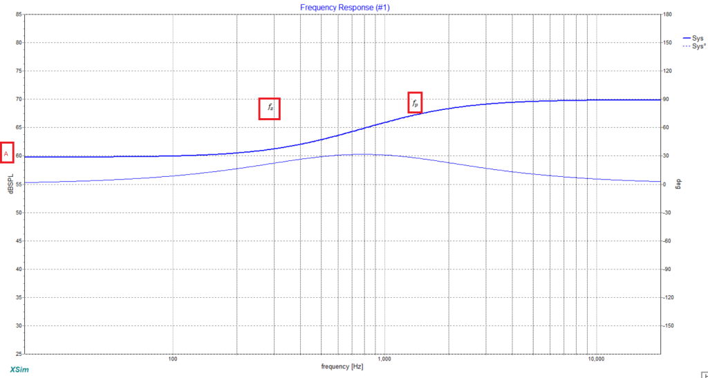
LSF Boost/HSF Cut HSF Boost/LSF Cut
The other reason to define high and low shelf is so that people understand which part of the signal you are targeting for modification. It will help to convey your goals in the implementation of the filter, which always seems to help when trying to get advice.
Passive Shelf Filter Layout
This section will discuss the implementation of each filter. That is, this will discuss what components are needed for the filter and how they roughly shape the curve, without examining the math.
Low Shelf Cut Filter/High Shelf Boost Filter
To start, we will look at the LSF cut/HSF Boost variant. For this, you will be running a resistor and a capacitor in parallel in the positive line of the circuit path while using a resistor to then run between the positive line after the parallel circuitry to the negative/ground line. See the image for layout.
LSF Cut/HSF Boost
What does each component do? First, the capacitor moves left to right where the shift happens for increasing or attenuating the signal. Second, the resistor in parallel on the positive line raises and lowers the lower frequency sensitivity. Third, the resistor bridging the positive line to the negative line/ground also raises and lowers the frequency sensitivity of the lower end, but it also has a soft effect on the curvature going from the low to the high frequency set.
Low Shelf Boost Filter/High Shelf Cut Filter
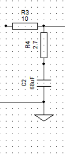
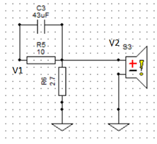
Next we have the LSF Boost/HSF Cut filter. This is comprised of a resistor in the positive line along with a resistor followed by a capacitor in series connecting the positive line to the negative/ground line. See image below.
LSF Boost/HSF Cut
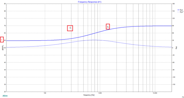
The resistor on the positive line moves the entire signal up and down. This makes sense because resistors attenuate the signal. The resistor in the bridging between the positive line and negative/ground line moves the frequencies of the high end up and down. And the capacitor is used to shift where the slope is on the frequency response (moves the slope left and right).
The Math
HSF Boost/LSF Cut Math Equations
V1 and V2 Equation Variables for HSF Boost/LSF Cut HSF Boost/LSF Cut Equation Variables A, fz, and fpLow Shelf Filter Boost/High Shelf Filter Cut Math EquationsV1 and V2 Equation Variables for Low Shelf Boost Filter/High Shelf Cut Filter Low Shelf Boost Filter/High Shelf Cut Filter Equation Variables A, fp, and fz
I won’t go through all of the math. Even though the pictures show the resistors and capacitors used, they carry different numbers from the equation. Just remember that R1 is always in line with the positive line and R2 is always bridging the positive line to the negative/ground line. A is the amount that the lower sensitivity of the frequency response is at. Finally, fz is the lower sensitivity end of the slope and fp is the higher end of the slope.
Conclusion
If you are unsure, you can always open XSim and shape the curve with the rough description given in the last section of this article on what each component in the filter does to the curve shape. You then can plug in what you got into the equations to see them operate in that way, which may help to use it to solve for the values of the components in the future. Sometimes just seeing it work with known variables helps to start thinking about solving for the variables when using the equations. Also, you can cascade these, if you want to do a multi-order shelving filter.
And if you would like to take deeper dives into shelving filters, I suggest you might check here, here, and here. If you instead would like to implement a shelving filter through DSP, you might check out the forums and ask for me if you need help finding it in sigmastudio, or to generally learn more about DSP.
Adam J Cain
Author, Attorney (non-practicing), Philosopher, Burgeoning Audiophile and Woodworker
The Klipsch KL-650 THX Ultra II were iconic in the Home Theater Industry. It was one of the first times I remember that you could affordably buy speakers that were truly designed for a small movie theater, for your own home theater. However, when I say affordably, they still cost around $$3500 for a pair! And for the entire system…a cool $13,000! And although, for movie theater speakers, that isn’t crazy, it is still a lot more than I want to spend on my Home Theater. And truthfully, I think that is the same as most other people. SO why not build some, for a lot cheaper.
Led Fun LED’s have the ability to make a speaker project go from blah, to wow! They really can be the last touch you need to make a project turn heads. The only problem most people have is how to implement them. There area a few ways to do this. Let’s first start with the…
If you have been around speaker building long enough, you will find out that there are many arguments made about what shape is best to use for an enclosure. Some people claim it is a cube, others rectangle, cylinder and even a sphere. And each of these believe their shape is best to reduce reflections. …
So I found this awesome site today which helps you design and build a horn speaker. Many people like the idea of a Horn speaker, but do not know where to start. That is where this site comes into play. There is a free download for an Excel spreadsheet which will actually calculate all the…
I have used the ND65-4 in a few builds and have been pretty impressed with them. Most of the time, I just used them in a sealed enclosure, as I tried to keep the size down. This time, I decided to use a 1″ port. Video [youtube=https://www.youtube.com/watch?v=UfRiuS3CSt4&w=320&h=266] Inspiration My friend was having a home warming…
After completing the Reveal, I was so impressed with them, I decided to make an MTM version. This MTM version, is a sealed speaker that was designed specifically with Home Theater in mind. I also tested this to see how it would work in a horizontal position for those who may want to make this…